Ứng dụng mạng không dây ZigBee cho hệ thống xe tự vận hành AGV
In recent years, unmanned factory or warehouse automation systems has become popular. Automatic Guided Vehicles (AGV) are used to transport goods to and from the product lines, storage systems, and transfer stations, etc. If there are several AGVs in the same location, vehicle driving routes may overlap. Consequently, preventing route conflict is an important issue.
Description
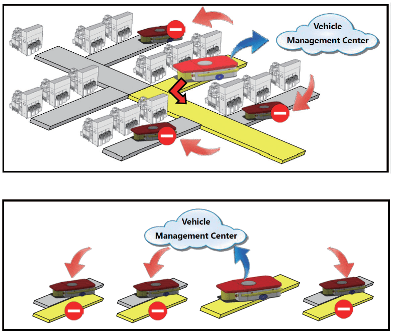
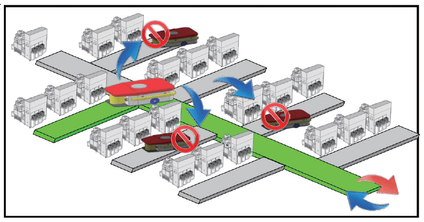
When an AGV is about to enter a restricted area, such as the main road, track or elevator, the AGV needs to send a request to the vehicle management center for permission to enter. Once the center approves the request, no other AGV will be able to enter that area until the original AGV departs and the management center releases control. Other AGVs can then apply to enter that restricted area.
Based on the above application, each AGV can send a message to the vehicle management center, and can send an area disabled message to other AGVs in the region. The vehicle management center can be seen as a type of virtual cloud with a M2M (Machine to Machine) architecture. The AGV is a mobile device, so it needs a wireless device that contains M2M architecture to carry out the message exchanges.
The ZT-IOG System is Suitable for the AGV Route Management System
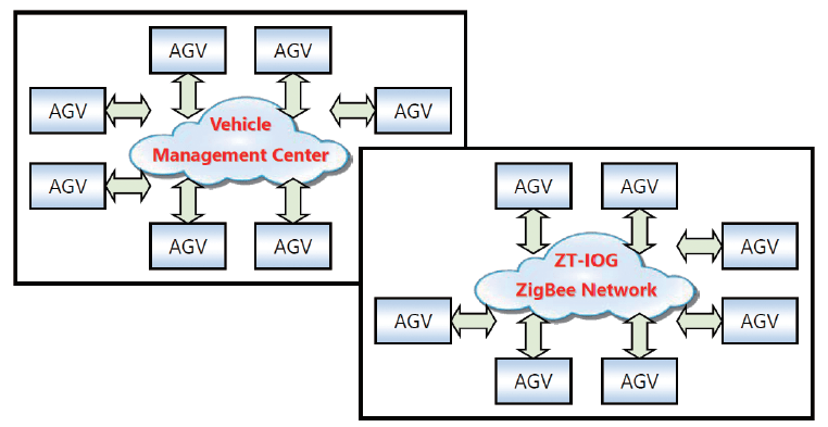
ZigBee network
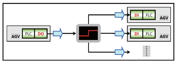
Event Triggering Modes
An ZT-IOG network is a multi-to-multi I/O Pair Connection architecture, so any ZT-IOG module connected to the ZigBee network can be used to change the I/O channel state of the other ZT-IOG modules. This feature meets the requirements of this application, and thus achieves the purpose of the message exchange.
Message Exchange
If an AGV is about to enter a restricted area, it must first determine the current status of the area, and then update the status. In this situation, the “On/Off” states from the DI/DO channels can be used to simulate an “occupied/idle” status message, and then notify other AGVs in the area via the I/O channel status, thereby reaching the goal of the route management system.
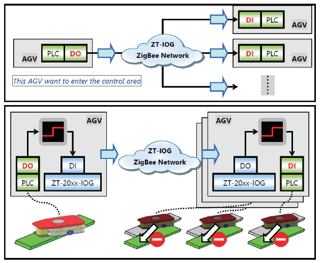
Application Architecture (i)
There are two levels in the architecture of the AGV route management system, including:
(1) Control level: the AGV is equipped with a PLC, PAC or IPC controller, etc. In addition to controlling the movement of the goods and the vehicle motion, it also manages the message exchanges among the vehicles in order to determine the status of the current route and calculate the required timing for any vehicles about to enter the restricted area.
(2) Message exchange level: The ZT-IOG network can function as a medium for exchanging messages.
Not only can the “occupied/idle” status be simulated via the “On/Off” I/O status from the ZT-IOG module, but it can also automatically update the I/O state via the ZigBee wireless network, thereby breaking geographical limitations.
The Actual Operation
If an AGV wants to enter the restricted area, its PLC will output a “high” state at the control level to trigger the DI on the ZT-IOG module. Meanwhile, the DO for the other ZT-IOG modules in the network will change to “high” based on the “Level Mode” Updating Logic, and will then trigger the DI on the PLC for all vehicles and set it to “high”. This means that the usage status will be set to “occupied”, so that other vehicles cannot enter this area. Once this AGV has left the restricted area, its PLC will cancel the “high” level state on the ZT-IOG modules, which means that other AGVs can send a request to enter the area.
Message Exchange
The Actual Operation
Overall Architecture Diagram
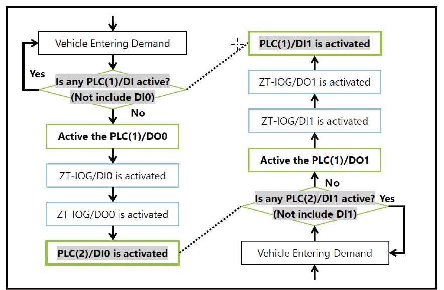
Applications Logic Flow Chart
Application Architecture (ii)
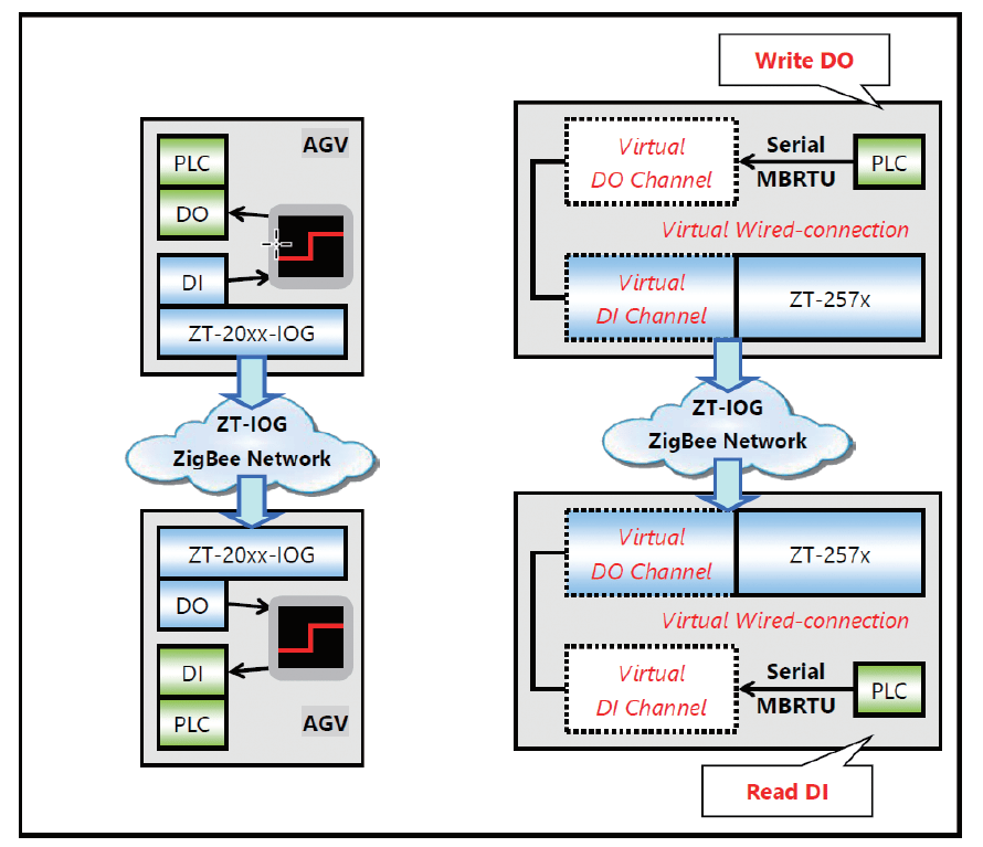
When considering the application and architecture described above, in addition to using the “physical I/O” on the ZT-20xx-IOG modules to simulate the “occupied/idle” status via the “On/Off” state, you can also use the serial port communication (RS-232/RS-485) on the PLC to achieve the message exchange function.
The ZT-257x module provides 280 pairs of virtual Digital Input/Output channels that can access the virtual I/O channels via the Modbus RTU protocol, and the virtual I/O channel states can still operate in Pair-connection mode with the physical I/O channel states. The DI/DO on the module works in the same way.
For a more detailed description, please refer to discussion related to IOG mode for ZT-2570 and ZT-2571 modules by clicking the link below.
Zigbee / ZT_series
Application Architecture
Related Products
|
|