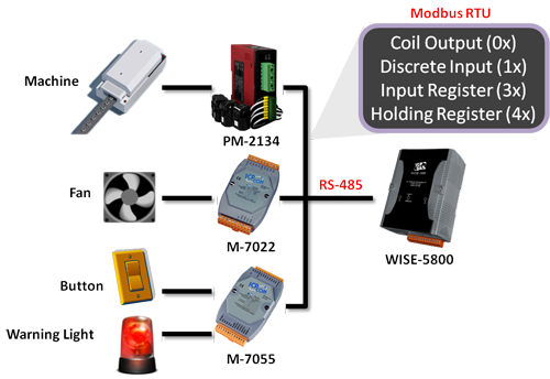
Through Modbus RTU protocol, WISE-580x, WISE-52xx and WISE-224x is able to read or write 4 types of Modbus data (Coil Output, Discrete Input, Input Register and Holding Register) from the Modbus RTU Slave modules to the WISE-580x, WISE-52xx and WISE-224x. And by WISE IF-THEN-ELSE rule engine, it allows to perform automation control operation on the devices. And with SCADA software, it also allows to monitor and control the Modbus RTU device retrieved information on the WISE-580x, WISE-52xx and WISE-224x.
 The comparison table of WISE-580x, WISE-580x-MTCP, WISE-52xx and WISE-224x in I/O module connection is as below:
| I/O Module Support | WISE-580x | WISE-580x-MTCP | WISE-52xx/WISE-224x |
| Local I/O Interface | XW-Board | XW-Board | XV-Board |
| Remote I/O Interface by RS485 |
I-7000 modules (up to 16) or Modbus RTU Slave modules (up to 10) |
No | I-7000/DL DCON modules (up to 16) and Modbus RTU Slave modules (up to 16) |
| Remote I/O Interface by Ethernet |
No | Modbus TCP Slave modules (up to 7) |
Modbus TCP Slave modules (up to 16) |
Modbus RTU Module Setting
WISE-580x
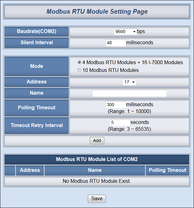
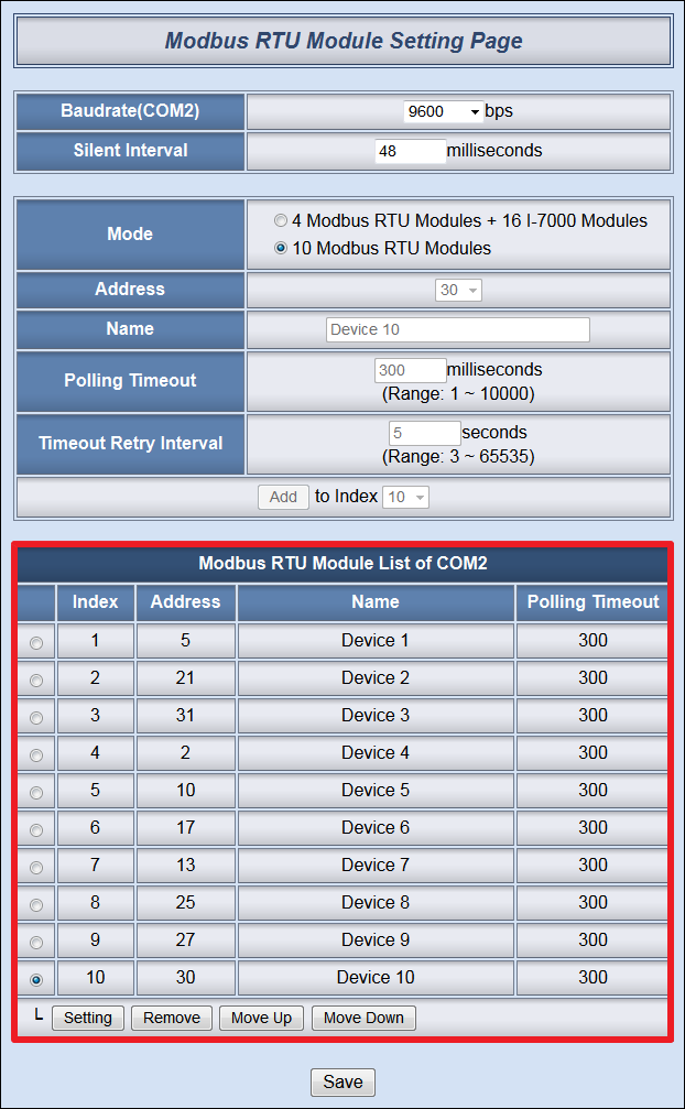
In Modbus RTU Modules Setting page, it allows to perform parameters settings and related configuration of the Modbus RTU Slave modules for use in the IF-THEN-ELSE rules edition. Each WISE-580x can connect to either up to 4 or 10 Modbus RTU Slave modules – the maximum quantity it allows to connect to depends on the mode selected. The setting page is shown as follow:
Follow the following steps:
-
-
In the “Baudrate(COM2)” field, select the WISE-580x COM2 data transmission Baudrate from the drop down list. The Baudrate has to be set the same as the Baudrate of Modbus RTU Slave modules. Please note: on the I-7000 Module Setting page, there is a COM2 Baudrate setting as well, please note that all I-7000 modules and Modbus RTU Slave modules that are connected to the WISE-580x COM2 must be set to the same Baudrate.
-
Select the data transmission Baudrate for WISE-580x COM2, and then the system will automatically provide a proper value in the “Silent Interval” field. For each Modbus RTU Slave device has different Modbus command process capability, the response time for sending result from Modbus RTU Slave device to controller might be different. You can adjust this value to most appropriate time interval, such as: extend this value to make sure every Modbus RTU Slave device connected to the WISE-580x has enough time to process the Modbus command, or shorten this value to improve the efficient of the poll mechanism between Modbus RTU Slave device and WISE-580x.
-
In the “Mode” field, select the I/O module connection mode for this WISE-580x. There are two options; if you select “4 Modbus RTU Modules + 16 I-7000 Modules”, the address of the Modbus RTU Slave module has to be set between 17~20. If the option “10 Modbus RTU Modules” is selected, this WISE-580x is set to connect to Modbus RTU Slave modules only and the address of the Modbus RTU Slave module in this mode has to be set between 1~32.
-
In the “Address” field, select the correct address for the Modbus RTU Slave module. Please note: the configuration of the address must be the same as the Modbus RTU Slave module address setting.
-
In the “Name” field, input the Modbus RTU Slave module name. This name will be used in IF-THEN-ELSE rule edition.
-
Input the “Polling Timeout” field. The “Polling Timeout” indicates the time interval for WISE-580x to send command to the Modbus RTU Slave module and wait for the response, the unit is millisecond.
-
Input the “Timeout Retry Interval” field. The “Timeout Retry Interval” indicates the time interval for WISE-580x to resend command to Modbus RTU Slave module when it’s in the timeout status when performing communication between WISE-580x and Modbus RTU Slave module. The unit is second.
-
After finish the settings of ”Baudrate(COM2)”, “Silent Interval”, ”Mode”, ”Address”, “Name”, “Polling Timeout” and ”Timeout Retry Interval”, click “Add” button. The new Modbus RTU Slave module will be added to the module list. The order of the Modbus RTU Slave module will vary according to the mode selected. If you select the mode that supports 4 Modbus RTU modules, the Modbus RTU Slave modules will be added in the order of the address 17~20. If you select the mode that supports 10 Modbus RTU modules, the order of the Modbus RTU Slave module will correspond to the Index number the Modbus RTU module being assigned (not correspond to the RS-485 address). So before you add the module, you must assign a specific Index (1-10) to a specific Modbus RTU module. According to the Index being assigned, the I/O channel data of the module will be saved in the corresponding WISE-580x Modbus address table, for more detailed information, please refer to Appendix 1 in user manual.
-
The following are examples of the Modbus RTU Slave module lists.
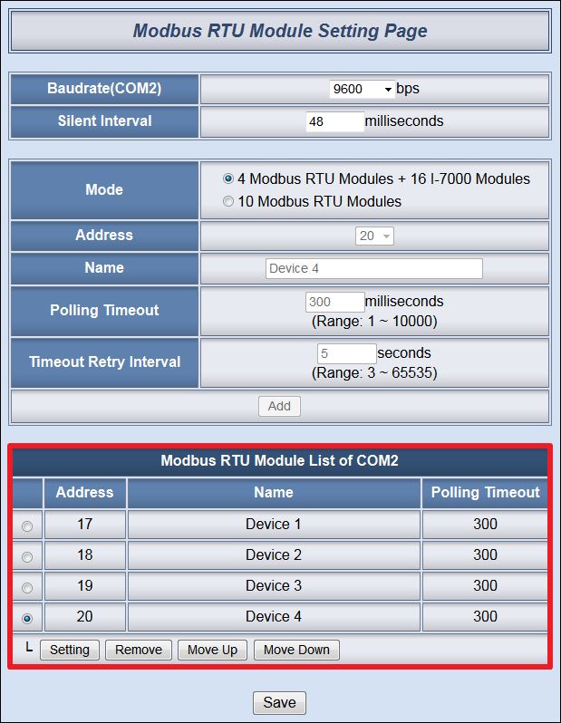
Modbus RTU Slave Module List for “4 Modbus RTU Modules + 16 I-7000 Modules”
▲ Modbus RTU Slave Module List for “10 Modbus RTU Modules”
-
Click on the Modbus RTU Slave module on the module list and click “Setting” button to get in to the Coil Output, Discrete Input, Input Register and Holding Register setting page to edit settings. To remove the Modbus RTU Slave module, select the module you would like to remove and click “Remove” button. To relocate Modbus RTU Slave to other address, click “Move Up” or “Move Down” to move the Modbus RTU Slave module to the desired address(for “4 Modbus RTU Modules + 16 I-7000 Modules” mode) or the desired Index(for “10 Modbus RTU Modules” mode).
-
After all Modbus RTU Slave module settings are completed, click “Save” button to save the changes.
Modbus RTU Slave Attribute Setting
The detailed configuration page of Coil Output, Discrete Input,Input Register and Holding Register for each Modbus RTU device is shown as below:
WISE-580x:
WISE-52xx/WISE-224x:

Follow the following steps:
-
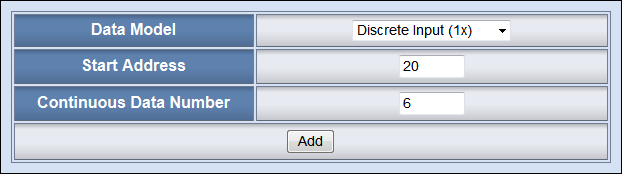
Data Model: WISE-580x, WISE-52xx and WISE-224x offers 4 Data Model selections to match the Modbus RTU Slave module configuration. The Data Model list is as follow.
| Data Model | The Modbus Address of Modbus RTU Slave Modules | Data Type | |
| Coil Output | 0xxxx | ||
| Discrete Input | 1xxxx | ||
| Input Register | 3xxxx |
|
-
Start Address: Allows to set up the starting address of Coil Output (0x) on the Modbus RTU Slave module you would like to retrieve.
-
Continuous Data Number/Data Number: After finishing the Start Address setting, specify the Continuous Data Number/Data Number, it is the number of Coil Output data you would like to retrieve from the Start Address.
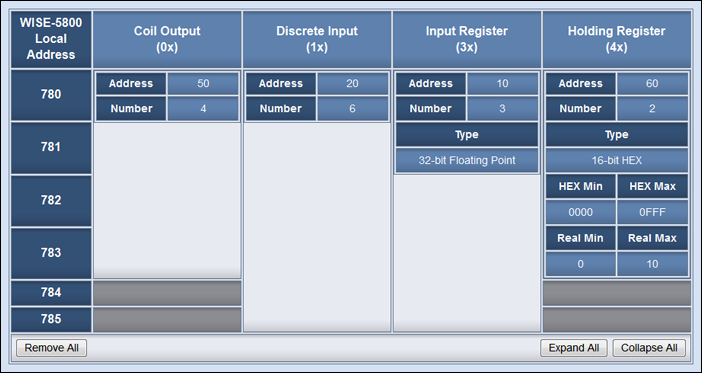
After finishing the “Start Address” and “Continuous Data Number/Data Number” setting, click on “Add” button. A new Coil Output address block will be added to the Modbus address mapping table (shown as below). All added address blocks will be located in sequences staring from the Starting Address. Please note: The address number on the first column “Local Address” means the local Modbus address of WISE-580x, WISE-52xx and WISE-224x to keep the retrieved data.
WISE-580x:
WISE-52xx/WISE-224x:
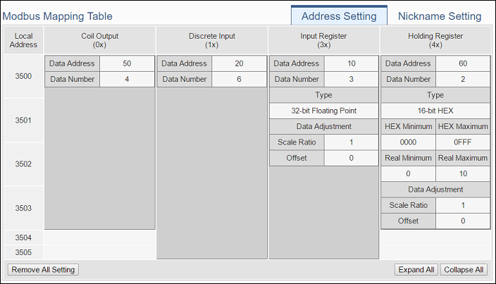
Using the figure above as an example, the allocation of the Modbus Address in WISE-580x, WISE-52xx and WISE-224x for the Coil Output setting of this Modbus RTU module is shown as below:
| Coil Output Index | The Modbus Address in Modbus RTU Module | The mapping Modbus Address in WISE-580x | The mapping Modbus Address in WISE-52xx WISE-224x |
| 1 | 00050 | 00780 | 03500 |
| 2 | 00051 | 00781 | 03501 |
| 3 | 00052 | 00782 | 03502 |
| 4 | 00053 | 00783 | 03503 |
The allocation of the Modbus Address in WISE-580x, WISE-52xx and WISE-224x for the Discrete Input setting of this Modbus RTU module is shown as below:
| Discrete Input Index | The Modbus Address in Modbus RTU Module | The mapping Modbus Address in WISE-580x | The mapping Modbus Address in WISE-52xx WISE-224x |
| 1 | 10020 | 10780 | 13500 |
| 2 | 10021 | 10781 | 13501 |
| 3 | 10022 | 10782 | 13502 |
| 4 | 10023 | 10783 | 13503 |
| 5 | 10024 | 10784 | 13504 |
| 6 | 10025 | 10785 | 13505 |
The allocation of the Modbus Address in WISE-580x, WISE-52xx and WISE-224x for the Input Register setting of this Modbus RTU module is shown as below:
| Input Register Index | The Modbus Address in Modbus RTU Module | The mapping Modbus Address in WISE-580x | The mapping Modbus Address in WISE-52xx WISE-224x |
| 1 | 30010 | 30780 | 33500 |
| 2 | 30012 | 30782 | 33502 |
| 3 | 30014 | 30784 | 33504 |
The allocation of the Modbus Address in WISE-580x, WISE-52xx and WISE-224x for the Holding Register setting of this Modbus RTU module is shown as below:
| Holding Register Index | The Modbus Address in Modbus RTU Module | The mapping Modbus Address in WISE-580x | The mapping Modbus Address in WISE-52xx WISE-224x |
| 1 | 40060 | 40780 | 43500 |
| 2 | 40061 | 40782 | 43502 |
(The number of Modbus address setting blocks will affect the data update rate for the Modbus RTU Slave module. Please minimize the number of Modbus address setting blocks; merge the conjunctive setting blocks to speed up the data update rate for the communication between WISE-580x/WISE-52xx/WISE-224x and Modbus RTU Slave module.)
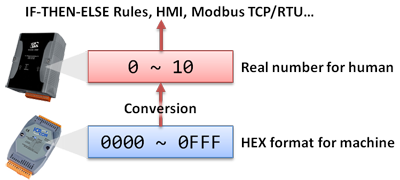
HEX Conversion
If the Modbus RTU Slave device provides HEX data only, WISE-580x, WISE-52xx and WISE-224x allows to transfer the HEX value to decimal value in floating point so that the value can be used in IF-THEN-ELSE rules edition. The value retrieved from WISE-580x, WISE-52xx and WISE-224x via Modbus TCP/RTU can be transferred to more-easy-to-read decimal value in floating point automatically as well (the floating point will take two local addresses).
When you select HEX as the data type, you will be required to input the HEX data range and the corresponding decimal data range. WISE-580x, WISE-52xx and WISE-224x will transfer the HEX to decimal value automatically when performing read/write operations.
Modbus RTU Slave Rule Setting
-
-
Coil Output Condition:
-
Identify the status of Coil Output to be ON or OFF, if the result matches the evaluation criteria, the Action will be executed.
| Coil Output | Operator | Description | Condition Statements |
| Coil Output State of Address N | ON | Identify if the state of Coil Output is ON | continue to be TRUE when the status matches the criteria |
| OFF | Identify if the state of Coil Output is OFF |
-
-
Discrete Input Condition:
-
Identify the status of Discrete Input to be ON or OFF, if the result matches the evaluation criteria, the Action will be executed.
| Discrete Input | Operator | Description | Condition Statements |
| Discrete Input State of Address N | ON | Identify if the state of Discrete Input is ON | continue to be TRUE when the status matches the criteria |
| OFF | Identify if the state of Discrete Input is OFF |
-
-
Input Register Condition:
-
Identify the value of Input Register to be equal to, greater than, less than, equal to or greater than, equal to or less than the “Variable”, if the result matches the evaluation criteria, the Action will be executed.
| Input Register | Operator | Variable | Description | Condition Statements |
| Input Register Value of Address N | = > < ≥ ≤ |
User-Defined Value | Using a user-defined value to compare with Input Register value of address N. | continue to be TRUE when the status matches the criteria |
| Internal Register | Using the internal register value to compare with Input Register value of address N. | |||
| AI Channel Value | Using AI channel values of module to compare with Input Register value of address N. | |||
| AO Channel Value | Using AO channel values of module to compare with Input Register value of address N. | |||
| Input Register Value | Using input register values of module to compare with Input Register value of address N. | |||
| Holding Register Value | Using holding register values of module to compare with Input Register value of address N. |
-
-
Holding Register Condition:
-
Identify the value of Holding Register to be equal to, greater than, less than, equal to or greater than, equal to or less than the “Variable”, if the result matches the evaluation criteria, the Action will be executed.
| Holding Register | Operator | Variable | Description | Condition Statements |
| Holding Register Value of Address N | = > < ≥ ≤ |
User-Defined Value | Using a user-defined value to compare with Holding Register value of address N. | continue to be TRUE when the status matches the criteria |
| Internal Register | Using the internal register value to compare with Holding Register value of address N. | |||
| AI Channel Value | Using AI channel values of module to compare with Holding Register value of address N. | |||
| AO Channel Value | Using AO channel values of module to compare with Holding Register value of address N. | |||
| Input Register Value | Using input register values of module to compare with Holding Register value of address N. | |||
| Holding Register Value | Using holding register values of module to compare with Holding Register value of address N. |
-
-
Coil Output Action:
-
Change the Coil Output status to specified status. The status can be set as “OFF” or “ON”.
| Coil Output | Action | Description | Execution Type |
| Coil Output State of Address N | ON | Change the DO Channel status to be ON | One Time / Repeat |
| OFF | Change the DO Channel status to be OFF |
-
-
Holding Register Action:
-
Users can modify the Holding Register value in the THEN/ELSE Action statement.
| Holding Register | Operator | Variable | Description | Execution Type |
| Holding Register Value of Address N | = += -= |
User-Defined Value | The value defined by user. | One Time / Repeat |
| Internal Register | One of the Internal register value of the module. | |||
| AI Channel Value | One of the AI channel value of the module. | |||
| AO Channel Value | One of the AO channel value of the module. | |||
| Input Register Value | One of the Input Register value of the module. | |||
| Holding Register Value | One of the Holding Register value of the module. | |||
| Operator Description | ||||
| = | Assign the new Holding Register value as the value in “Varibale” field. | |||
| += | Assign the new Holding Register value as the original Holding Register value plus the value in “Varibale” field. | |||
| -= | Assign the new Holding Register value as the original Holding Register value minus the value in “Varibale” field. | |||
Modbus RTU Master Application Example
| Scenario | Example Document | ||
|
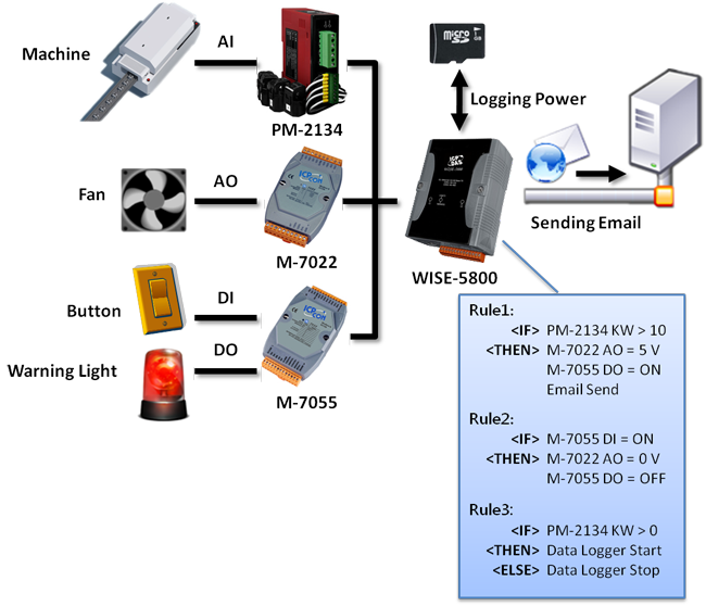
Assume a factory requires electricity monitoring over the devices; ICP DAS PM-2134 power meter is used to monitor the instantaneous power (KW) value of the devices; and the KW value will be transmitted to WISE-5800 via Modbus RTU protocol. At the same time, the WISE-5800 is connected to M-7055 and M-7022 modules. The M-7055 is connected to one warning light and an emergency switch. The M-7022 module is connected to a cooling fan. When the instantaneous power (KW) value exceeds 10KW, WISE-5800 will send command to M-7055 to turn on the warning light to notify the related personal for emergency response. At the same time, the M-7022 will start the cooling fan to reduce the heat and send email to related personnel. After the emergency has been taken care of by the related personnel, he/she can push the emergency switch to turn off the warning light and cooling fan, the status of the emergency switch will also be sent to WISE-5800. Meanwhile, the cumulative power(KWh) value of this device will be recorded every 5 minutes, and the logger file will be sent to FTP server at midnight 0 o’clock each day for further administration management and data analysis. |
|

Graphic Illustration