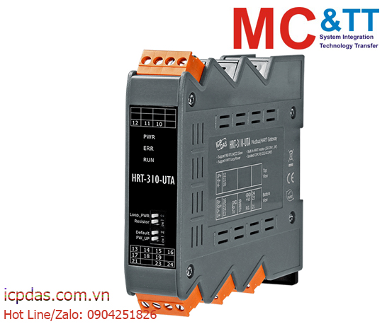
Bộ chuyển đổi cổng Modbus RTU/ASCII sang HART ICP DAS HRT-310-UTA CR
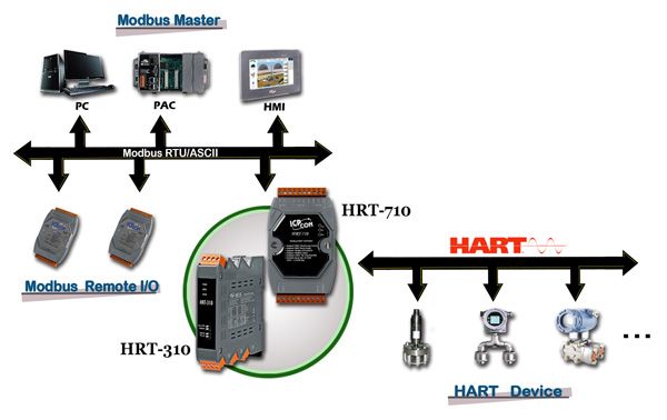
The HRT-310-UTA Gateway is specially designed for the master device of HART protocol. It allows the Modbus master to access the HART devices. These HART devices may be a transmitter, an actuator and so forth. In addition, we also provide the software utility, HG_Tool, for module configuration and HART device diagnosis. By using these modules, users can integrate their HART devices into Modbus network easily and quickly.
| Model |
HRT-710 |
HRT-310 |
| Din Rail Installation |
Horizontal |
Upright |
| HART Signal |
Standard |
Enhanced send/receive signal
(For long distance comm.) |
| Loop Power |
No |
Support
(module provides +30V output) |
| Built-In Resistor |
250 Ohm (1/4W) |
250 Ohm (1W) |

• Industrial Automation
• Factory Automation
• Process Automation
• Etc…
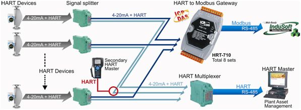
HRT-310-UTA, a HART master to Modbus slave gateway, is applied to integrate the information from these HART flow meters into the customer’s HMI system. Through the HRT-310, all of the HART flow meters will be regarded as Modbus slave devices and the HMI system can use the built-in Modbus RTU communication to access these HART flow meters easily.
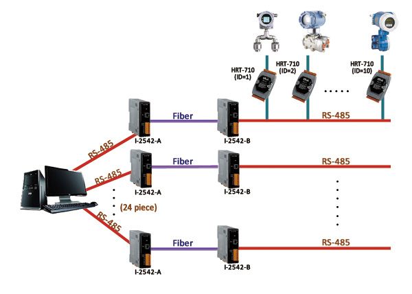
More than 250 HART device information needs to be integrated to surveillance center. In PC side, uses 3 pieces of PCI cards (VXC-148U, for 24 channels RS-485 expansion). I-2542A and I-2542B (RS-485 to Fiber) are used in every RS-485 channel to extend RS-485 communication distance. There are about 20 pieces of HRT-310-UTA modules used in every RS-485 channel with the different station ID. Through the structure, SCADA or HMI system can integrate all HART device information via Modbus protocol easily and quickly.
- Provide the system and communication configuration of HRT-310-UTA
- Provide the Modbus address table for HART command data
- Provide the diagnostic information of HRT-310-UTA module and HART device
- Provide send / receive HART command to access HART device
- Provide “Load/Save” module configuration file to apply to other HRT-310-UTA quickly
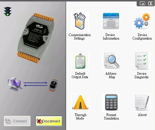
Modules Support
Support the following Modbus commands.
| Code |
Name |
Description |
| 01 |
Read Coil Status |
Read the ON/OFF status of discrete outputs in the slave |
| 02 |
Read Input Status |
Read the ON/OFF status of discrete inputs in the slave |
| 03 |
Read Holding Registers |
Read the binary contents of holding registers in the slave |
| 04 |
Read Input Registers |
Read the binary contents of input registers in the slave |
| 05 |
Force Single Coil |
Write a single output to either ON or OFF in the slave |
| 06 |
Preset Single Register |
Write an integer value into a single register in the slave |
| 15 |
Force Multi. Coils |
Write each coil in the sequence of coils to either ON or OFF in the slave |
| 16 |
Preset Multi. Registers |
Write a block of contiguous registers in the slave |
