Nội dung
AI Attribute Introduction
WISE offers a variety of controllers that enables connecting with all kinds of AI (Analog Input) signals such as Voltage, Current, Sensor Input, etc.. AI channel supports Deadband and Scale settings. And for Thermocouple signal input, it supports Fahrenheit/Celsius conversion function. In the logic rule settings, the AI Channel value can be compared with the value of the other AI Channel, Internal Register, or a specific value by operators “=”, “>”, “<”, “≥” or “≤”; the evaluation statement can be included in the IF Condition statements. With various functions provided, the logic edition work can be easier.
AI Attribute Setting
WISE-71xx, 72xx, 75xx, 790x
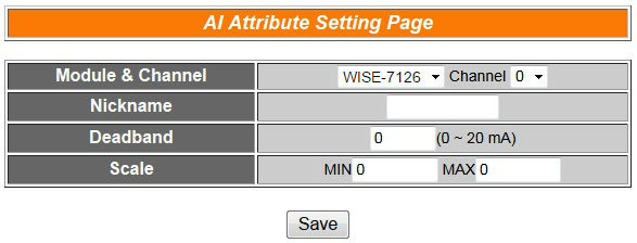
The AI attribute setting page is shown as below:
Follow the following steps:
-
Specify the channel you are going to configure by selecting channel index from the dropdown list of channel field in “Module & Channel” section.
-
Input Nickname for each I/O channel, this nickname will be displayed on the “Channel Status” page.
-
You can set the Deadband value of this AI channel in the “Deadband” field, on the right side of the Deadband field, the AI channel value range will be displayed, for WISE-4000, the channel value range will be 0-20mA. The default Deadband value is 0.
-
In the “Scale” field, AI channel raw data can be set to operate with linear proportion between “MIN” and “MAX” values. IF Condition will use the adjusted value in the logic Rule operation, and the AI value retrieved from Modbus TCP and Web HMI would be the adjusted value. The default value for MAX and MIN is 0, it mean disable the Scale function.
-
Repeat steps 1 ~ 4. After all AI Channel settings are completed, click “Save” button to save the changes.
WISE-580x
For XW-Board:
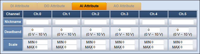
The XW-Board AI Channel Setting page is shown as follow: (using XW304 as an example)
The settings are as follow:
- Nickname:For users to define nicknames for each I/O channel, this nickname will be displayed on the “Channel Status” page.
- Deadband:In order to avoid signal oscillation that may result in instability to the status changes, the user can set up a Deadband value for the AI channel to reduce the oscillation effect to the channel value.
- Scale:In the “Scale” field, AI channel raw data can be set to operate with linear proportion between “MIN” and “MAX” values. The IF Condition will use the adjusted value in the logic Rule operation, and the AI value retrieved from Modbus TCP and “Channel Status” page would be the adjusted value. The default value for MAX and MIN is 0, it means the Scale function is disabled.
For I-7000 module:
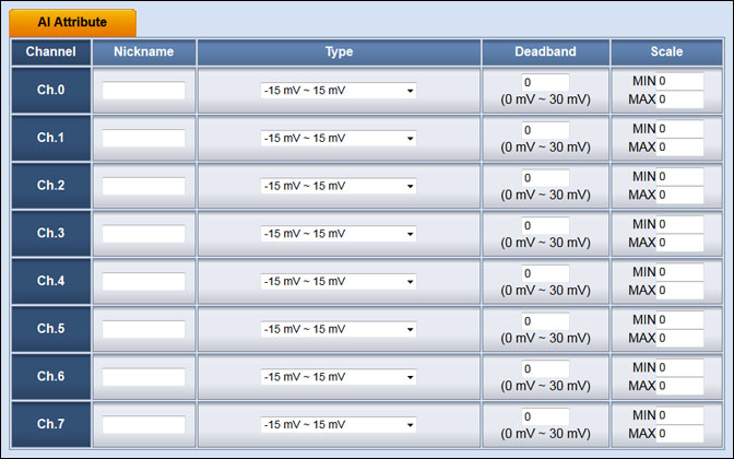
The I-7000 module AI Channel Setting page is shown as follow: (using I-7018 as an example)
The settings are as follow:
- Nickname:For users to define nicknames for each I/O channel, this nickname will be displayed on the “Channel Status” page.
- Type:Select the appropriate AI signal input type.
- Deadband:In order to avoid signal oscillation that may result in instability to the status changes, the user can set up a Deadband value for the AI channel to reduce the oscillation effect to the channel value.
- Scale:In the “Scale” field, AI channel raw data can be set to operate with linear proportion between “MIN” and “MAX” values. The IF Condition will use the adjusted value in the logic Rule operation, and the AI value retrieved from Modbus TCP and “Channel Status” page would be the adjusted value. The default value for MAX and MIN is 0, it means the Scale function is disabled.
WISE-52xx, 224x
For XV-Board:
The XV-Board AI Channel Setting page is shown as follow: (using XV310 as an example)
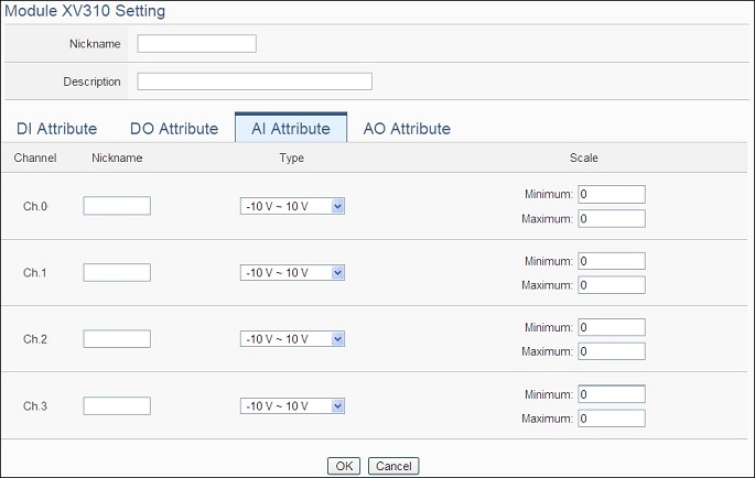
The settings are as follow:
- Nickname: For user to define nicknames for each I/O channel, these nicknames will be displayed on the “Channel Status” and “Rule Setting” pages.
- Type: Select the input signal type of the AI channel from the dropdown list.
- Scale: In the “Scale” field, AI channel raw data can be set to operate with linear proportion between “Minimum” and “Maximum” values. The IF Condition will use this already-adjusted value in the evaluation operation, and the AI value retrieved from the “Channel Status” page or Modbus Table via WISE-52xx/WISE-224x would be the adjusted value. The default value for Maximum and Minimum is 0, it means the Scale function is disabled.
For I-7000/DL DCON module:
The I-7000/DL DCON module AI channel setting interface is shown as below: (using I-7012 as an example)
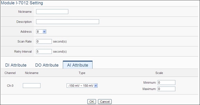
The settings are as follow:
-
- Nickname: For user to define nickname for the module and the I/O channels, these nicknames will be displayed on the “Channel Status” and “Rule Setting” pages.
- Description: The Description field provides a space for the user to make a brief description of this module.
- Address: The address will be the DCON address of this I-7000/DL DCON module, please make sure the address is the same as the settings of the module, if the setting is not accurate, the connection for WISE-52xx/WISE-224x to the I-7000/DL DCON module will be failed.
- Scan Rate: Input the time interval for WISE-52xx/WISE-224x to periodically retrieve the I/O channel data of this I-7000/DL DCON module, the setting range will be 0 ~ 65535 seconds.
- Retry Interval: The time interval to wait for WISE-52xx/WISE-224x to repeatedly send command again when WISE-52xx/WISE-224x sends command to the I-7000/DL DCON module and get no response. The unit will be second. The setting range will be 3 ~ 65535 seconds.
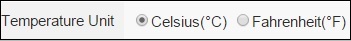
- Temperature Unit: Specify the temperature measurement unit for the modules that allows for temperature measurement, such as I-7005, I-7011, I-7013, I-7015, I-7018 and I-7019, the temperature units can be set as degree Celsius or degree Fahrenheit.
- Type: Select the input signal type of the AI channel from the dropdown list.
- Scale: In the “Scale” field, AI channel raw data can be set to operate with linear proportion between “Minimum” and “Maximum” values. The IF Condition will use this already-adjusted value in the evaluation operation, and the AI value retrieved from the “Channel Status” page or Modbus Table via WISE-52xx/WISE-224x would be the adjusted value. The default value for Maximum and Minimum is 0, it means the Scale function is disabled.
AI Deadband Operation
There are three operation styles for AI Deadband. Detail description is as below. The AI Channel setting in following examples is 0mA ~ 20mA.
-
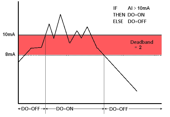
- When AI > or ≥ a numerical value:
Assuming the Deadband value is set to be 2 mA, and the following statements are defined in the related logic Rule: IF AI0>10mA, THEN DO=ON, ELSE DO=OFF, that means, when AI0 receives a signal that exceed 10mA, the DO channel will change to ON immediately. The DO channel will change to OFF immediately when the value reaches 8mA (10mA minus the Deadband value 2mA), as shown in the following figure.
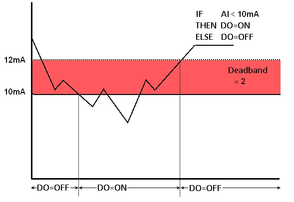
 When AI < or ≤ a numerical value :
Assuming the Deadband value is set to be 2 mA, and the following statements are defined in the related logic Rule: IF AI0<10mA, THEN DO=ON, ELSE DO=OFF, that means, when AI0 receives a signal which is lower than 10mA, the DO channel will change to ON immediately. The DO channel will change back to OFF immediately when the value reaches 12mA (10mA plus the Deadband value 2mA), as shown in the following figure.
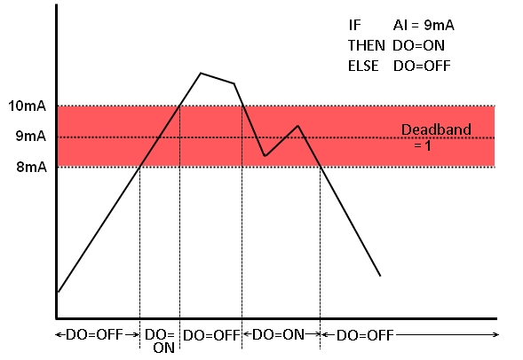
When AI = a numerical value:
Assuming the Deadband value is set to be 1 mA, and the following statements are defined in the related logic Rule: IF AI0 = 9mA, THEN DO=ON, ELSE DO=OFF, that means, when AI0 receives a signal between 8mA (9mA minus the deadband value 1mA) and 10mA (9mA plus the deadband value 1mA), the DO channel will change to ON immediately. However, when the AI0 channel value exceed 10mA, or is lower than 8mA, the DO channel will change to OFF, as shown in the following figure.
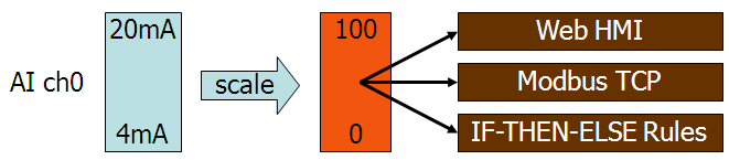
AI Scale Operation
WISE provides Scale function that maps raw values read from the AI channel by linear scaling approach to fit into the value between MIN and MAX values. Once the Scale value is set, this adjusted value will be used in the IF Condition evaluation. The value displayed on the Channel Status page and transmitted via Modbus TCP will be this adjusted value as well. The default value of MIN and MAX value will be 0, which means not using Scale function.
AI Attribute Rule Setting
-
-
AI Condition:
-
Identify the value of AI channel to be equal to, greater than, less than, equal to or greater than, equal to or less than the “Variable”, if the result matches the evaluation criteria, the Action will be executed.
| AI Channel | Operator | Variable | Description | Condition Statements |
| AI Value of Channel N | = > < ≥ ≤ |
User-Defined Value | Using a user-defined value to compare with the AI channel N value. | continue to be TRUE when the status matches the criteria |
| Internal Register | Using the internal register value to compare with the AI channel N value. | |||
| AI Channel Value | Using AI channel values of module to compare with the AI channel N value. | |||
| AO Channel Value | Using AO channel values of module to compare with the AI channel N value. | |||
| Input Register Value | Using input register values of module to compare with the AI channel N value. | |||
| Holding Register Value | Using holding register values of module to compare with the AI channel N value. |
AI Attribute Application Example
| Scenario | Example Document | ||||
|
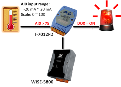
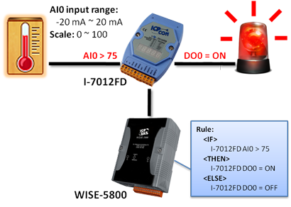
Assuming that a temperature sensor is connected to AI0 channel of a WISE controller, adjust the raw value read from AI0 by the Scale function via linear approach to fit in the new range (0 ~ 100). When the value of AI0 (the adjusted value) exceeds 75, the warning light will be turn on and will real time inform the related personnel; if the value is less than 75, the warning light will be off. |
|
||||
| Graphic Illustration | |||||
 |
|||||
