Active I/O Introduction
WISE-580x, WISE-52xx and WISE-224x equips the “Active I/O sending” function. There are two parts in this function: “I/O Data Table Configuration (I/O Data Table Setting)” and “Active Sending of I/O Data Table”. Even though WISE-580x, WISE-52xx and WISE-224x allows to connect with multiple I/O modules at the same time, however, the channel data of each I/O module that WISE-580x, WISE-52xx and WISE-224x received is located in the different Modbus Address memory block of WISE-580x, WISE-52xx and WISE-224x. Therefore, when using SCADA software to retrieve the data, the SCADA software must poll each I/O module’s channel data separately. It is impossible to poll all WISE-580x, WISE-52xx and WISE-224x I/O module’s channels data at one time. In order to improve the efficient of the data communication between WISE-580x/WISE-52xx/WISE-224x and SCADA software, WISE-580x, WISE-52xx and WISE-224x provides “I/O Data Table Configuration (Active I/O Sending)” function. It allows to copy the I/O channels data from different I/O modules and puts them into a continuous Modbus address memory block, and then SCADA software can retrieve all I/O channels data from different modules by using one single Modbus command. Comparing to traditional polling mechanism, it will greatly save time and polling attempts. In addition to the “I/O Data Table Configuration (I/O Data Table Setting)” function, WISE-580x, WISE-52xx and WISE-224x also provide the “Active sending of I/O Data Table” function. It allows WISE-580x, WISE-52xx and WISE-224x to actively send the content of I/O Data Table to SCADA software through Modbus TCP protocol without polling mechanism from SCADA software.
Please note: The SCADA software must equip the Modbus TCP Slave function to receive the content of I/O Data Table that sent by WISE-580x, WISE-52xx and WISE-224x.

Active I/O Setting
WISE-580x
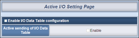
The active I/O setting page is shown as below:
Follow the following steps:
-
-
Select “Enable I/O Data Table configuration” to enable the I/O Data Table function, then the I/O Data Table and the configuration UI will be shown as follow:
-
-
-
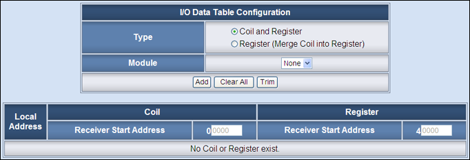
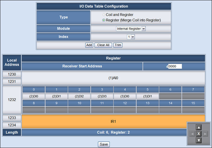
There are two data arrangement types for the I/O Data Table: ”Coil and Register” and “Register (Merge Coil into Register)”. In the ”Coil and Register” type, The I/O module’s DI/DO/Modbus Coil data will be saved in the Coil area of the I/O Data Table, and the I/O module’s AI/AO/Modbus Register/Internal Register data will be saved in the Register area of the I/O Data Table. If you select the “Register (Merge Coil into Register)” type, then the I/O module’s DI/DO/Modbus Coil data will be saved in the Register area of the I/O Data Table in binary format. Each Register can store 16 Coils data.
-
The “Module” field allows to select specific I/O module or Internal Register that will be used in the I/O Data Table; select the “Channel” and “Index” number from the drop down lists to edit the table configuration of the I/O module’s channel.
-
When you complete the setting of Module, Channel and Index, please click the “Add” button to add the channel of the I/O module into the I/O Data Table. You can use the Control Panel in the right-bottom of the I/O Data Table to “Move” or “Delete” the channel setting of the I/O Data Table. The “Clear All” button is used to clear all channel settings in the I/O Data Table. “Trim” button is used to remove all the excess space between the channel settings to make all channel settings of the I/O Data Table to be more compact.
In the I/O Data Table, the “Local Address” in the left side is the address for saving I/O Data Table in the WISE Modbus Address Table. The starting address is 1230(Base 0 & Decimal format). The maximum length is 300. Therefore, SCADA software can connect to the WISE Modbus address 01230 to inquire the first Coil data in the I/O Data Table, and connect to the WISE Modbus address 41230 to inquire the first Register data in the I/O Data Table. If the “Active sending of I/O Data Table” function is enabled, the “Receiver Start Address” in the upper area of the I/O Data Table is the address of the Receiver’s(SCADA software) Modbus starting address. The content of the I/O Data Table that WISE-580x send actively to Receiver’s(SCADA software with Modbus TCP Slave function) will be saved from the starting address. The naming rule of the channel inside the I/O Data Table is: (RS-485 Address) Channel Type + Channel Index. For example, (1)DI0 is for the DI0 channel of the I/O module with RS-485 address 1.
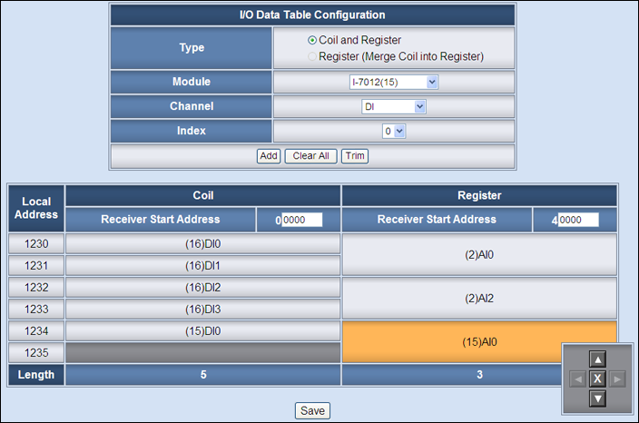
The following figure shows an example of the data arrangement of the I/O Data Table for the “Register (Merge Coil into Register)” type.
-
-
Enable the “Active sending of I/O Data Table”, then WISE-580x will actively send all the I/O Data Table‘s channels data to the SCADA software.
-
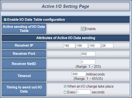
It is required to set the Receiver’s (SCADA software) IP address, the Modbus TCP Slave’s Port number and NetID of the Receiver’s, the Timeout value, and the type of “Timing to send out I/O Data”. There are two options for the “Timing to send out I/O Data”, one option is to send out the data when an I/O channel value change takes place, the other is to send out the data at periodic time schedule.
WISE-52xx, 224x
-
- I/O Data Table Setting
Setting page is shown as below:
Follow the following steps:
-
-
-
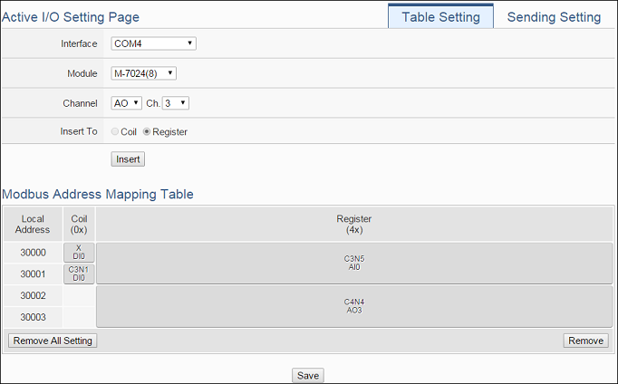
Click on the “Table Setting” tab at the right-upper corner of the Active I/O Sending setting page.
-
Select the “Interface”, “Module” and “Channel” from the dropdown list to identify the I/O channel which will be inserted into the I/O Data Table.
-
Please select the area which the I/O channel will be inserted into. There are two data types for the I/O Data Table: “Coil” and “Register”. The I/O module’s DI/DO/Coil Output/Discrete Input channel data can be saved in the “Coil” area of the I/O Data Table or be saved in the Register area of the I/O Data Table in binary format. Each Register can store 16 Coil data. The I/O module’s AI/AO/Input Register/Holding Register channel data and Internal Register data can be saved in the “Register” area of the I/O Data Table.
-
When you complete the setting of Interface, Module and Channel, please click the “Insert” button to add the channel of the I/O module into the I/O Data Table.
-
If you want to change the position of the I/O channel in the I/O Data Table, please left-click the I/O channel by mouse, and drag it up or down to arrange the new position of the I/O channel. When the I/O channel arrive the right position, release the mouse left-button to let the I/O channel be at the new location.
-
If you want to remove one I/O channel of the I/O Data Table, please click the I/O channel by mouse, then click the “Remove” button which is located at the right-lower corner of the I/O Data Table to remove the I/O channel.
-
If you want to remove all I/O channel of the I/O Data Table, please directly click the “Remove All Setting” button which is located at the left-lower corner of the I/O Data Table to remove all I/O channels.
-
After you finish the I/O Data Table settings, click “Save” button to save the settings.
-
- Active Sending of I/O Data Table
-
Setting page is shown as below:
Follow the following steps:
-
-
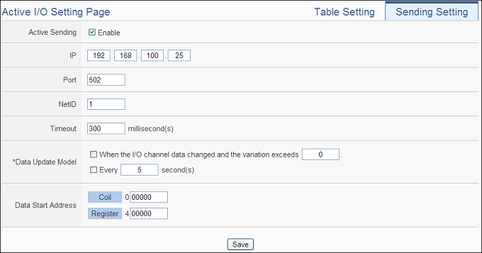
Click on the “Sending Setting” tab at the right-upper corner of the Active I/O Sending setting page.
-
Enable the “Active Sending” function, and then the setting interface will be shown as below.
-
Complete the receiver’s (SCADA software) IP address, the Modbus TCP Slave’s Port number, NetID and Timeout value setting. Make sure all the setting is the same as the settings of the receiver (SCADA software). If the setting is not accurate, the connection for WISE-52xx/WISE-224x to the receiver (SCADA software) will be failed.
-
Please select the timing to send back the data of I/O Data Table. There are two options for the “Data Update Model”, one option is to send out the data when the I/O channel data change takes place, the other is to send out the data at periodic time schedule. The two options can be enabled concurrently.
-
In the “Start Address” field, set up the start address which the receiver (SCADA software) will use to save the data of I/O Data Table from WISE-52xx/WISE-224x.
-
After you finish the “Active I/O sending” settings, click “Save” button to save the settings.’
-
Active I/O Application Example
| Scenario | Example Document | ||
|
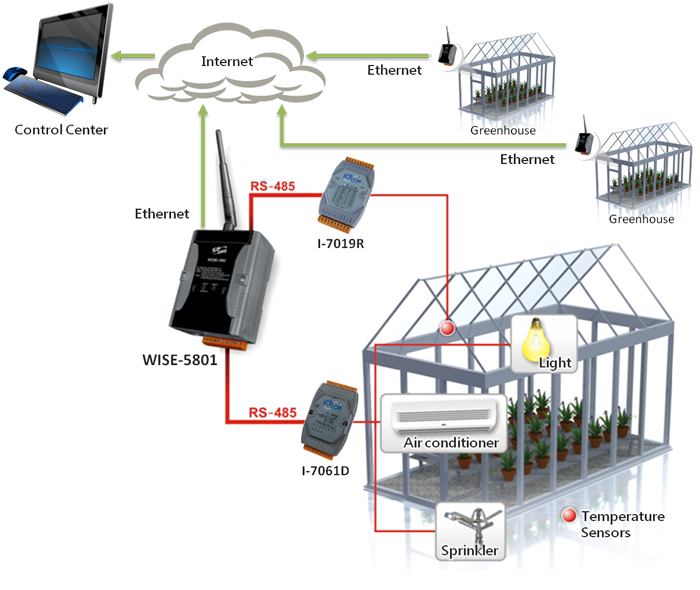
WISE-580x provides “Active I/O” function. Based on this function, WISE-580x can actively send (push) the channels value of the I/O modules that connected to WISE-580x to SCADA software (or HMI device) by event trigger (I/O channel value changed) or periodic cycle. This function greatly enhances the data communication efficiency between WISE-580x and SCADA software (or HMI device) via traditional polling mechanism. The following scenario assume using WISE-5801 controller in a greenhouse environment monitoring system. It is required to monitor the temperature and device’s status of various greenhouses at the same time. By the traditional polling mechanism, the control center must poll all controllers one by one to get the temperature and device’s status of each greenhouse. Now with this function, the WISE-580x controller in each greenhouse will actively send back the temperature value and device’s status it retrieves to the control center. In this scenario, the update rate is 5 second. |
|

Graphic Illustration